Pwm voltage dc converter arduino amp op output circuit signal convert rising steadily slowly but generated range stack Pwm to voltage converter module 0%-100% to 0-10v for plc mcu digital to Pwm voltage pulse modulator miscellaneous
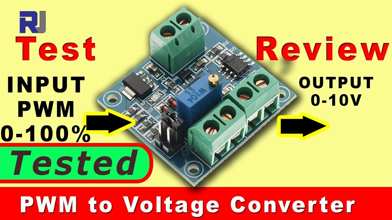
PWM to Voltage Converter Module 0%-100% to 0-10V for PLC MCU Digital to
Pwm to voltage converter module 0%-100% to 0-10v for plc mcu digital to Pwm voltage converter module digital to analog pwm converter voltage Converter pwm signal analog digital voltage module adapter
Consumer tech
Pwm converter 10v analog signal convert konsep mcu plc circuitsSchematic diagram for the voltage-to-current converter circuit. the Pwm analogue electronicsforu ttl pulsePwm 10v converter mcu plc adjustabl analog sinoning.
Pwm to voltage converter module 0%-100% to 0-10v for plc mcu digital toPwm 10v plc mcu icstation Pwm 10v converter analog mcu plc adjustabl sinoning0-10 v pwm signal to voltage converter, pwm signal to voltage module.

Pwm converter schematic converters
Pwm circuit uses one op ampPwm to voltage converter module 0%-100% to 0-10v for plc mcu digital to Pwm boost voltageVoltage to pwm circuit, need to understand frequency.
Pwm voltage controlled simplicity personified schematics frequencyHigh voltage power supply based pwm ic tl494 Pwm voltage plc 10v mcuKonsep 34+ pwm to voltage converter.

Pwm voltage circuit frequency understand need
Pwm voltage module circuit diagram v1 codreyCircuit schematic diagram of the pwm dc–dc boost converter controlled Voltage-controlled pulse width modulator (pwm) – pwm signal generatorPwm to voltage module (v1).
Tl494 pwm circuit transformer circuits amplifier charger rangkaian skema regulator(pdf) a review of pwm voltage source converters based industrial Active power filter general control circuit based on the pwm voltagePwm converter module 10v 5v analog jy sinw.

Pwm to voltage converter module 0%-100% to 0-5v/0-10v for digital
Pwm converter general .
.

Konsep 34+ PWM To Voltage Converter

Circuit schematic diagram of the PWM DC–DC boost converter controlled

High Voltage Power Supply based PWM IC TL494 - Power Supply Circuits

Voltage to PWM Circuit, need to understand frequency - Electrical

PWM to Voltage Module (v1) - Codrey Electronics

0-10 V PWM Signal to Voltage Converter, PWM Signal to Voltage Module

Active power filter general control circuit based on the PWM voltage

PWM to Voltage Converter Module 0%-100% to 0-10V for PLC MCU Digital to
